1
$\begingroup$

For this question, I have my own opinion and want to know whether it's correct or not. We know that ESC use pwm to control speed. For long range fixed wing at cruise speed, ESC may work at a relatively low duty cycle, let's say 20%. The average current on the input wire is the same as the output wire, let's say 5A. Suppose both the input wire and output wire have a resistance of 50mΩ, We may think the voltage drop on them both should be 5A*50mΩ=0.25v. But the charge go through the input wire in 20% of the time, that's 25A, so I think the voltage drop is going to be 1.25v. As for the output wire, modulated current from ESC should be relatively smooth and there should be lower voltage drop.
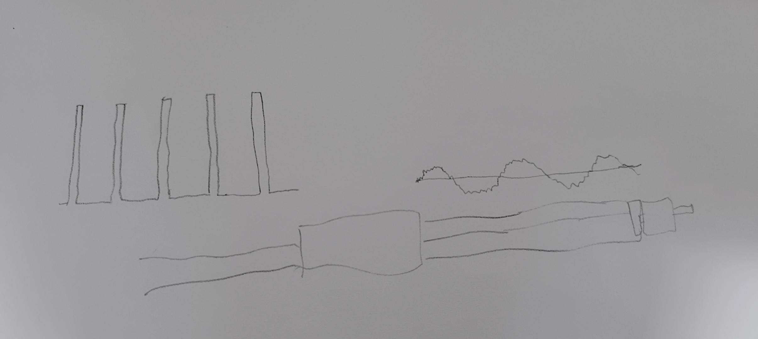
enter image description here I draw a picture to show this. Left is the current waveform of the input wire and right for the output. My opinion is, to increase total efficiency, it's better to use thicker wire on the input side of ESC, or put ESC closer to the battery. But I cannot afford a oscilloscope and cannot confirm this conclusion. This also lead me to think about what kv should I use. With same voltage and prop, lower kv leads to higher duty cycle, higher kv can make takeoff easier.

$\endgroup$
2
  • $\begingroup$ I think the motor Kv question should be moved to a separate post. $\endgroup$ Commented Nov 25, 2022 at 9:19
  • $\begingroup$ "But the charge go through the input wire in 20% of the time, that's 25A" What do you mean by this? The current is going through the wire at the same "speed" $\endgroup$ Commented Nov 28, 2022 at 13:55

2 Answers 2

0
$\begingroup$

The total energy used by the ESC is greater than the total energy supplied to the motor due to the minor joule losses in the ESC semiconductors and the amount of residual energy stored in the magnetic or electric fields of inductors or capacitors, which are also minority. The waveform output from the ESC depends on the control technology so it is not relevant in the discussion, but in the most common type of ESC it is trapezoidal/PWM so it is not particularly smooth (whatever it means). I don't think it makes sense to use losses of this magnitude to justify a difference in section between the input and output cables. Furthermore, precisely because of the bulk capacitors tipically present in the ESC and inductors in the motor there could be instantaneous differences between the current ratings drawn by the battery and those released trough the engine both in favor of one side or the other so a difference between the two wirings in the long run could probably be a bad thing rather than a good thing.

$\endgroup$
0
$\begingroup$

I think they should be the same, because the current in the input and output wires will be the same (and one output wire will have zero current)

I don't think the ESC can draw a large amount of current and store it, as you've drawn.

I also don't think that the voltage out is a sine wave. In order to supply anything other than battery voltage, the ESC would have to do more than just switch the power on and off. There would need to be some high-power DC/DC voltage conversion. All the ESCs I've seen only have 6 FETs, enough to connect each output to each input. I have connected an ESC to an oscilloscope (once, many years ago), and it was just switching battery voltage on and off.

Most fixed wing ESCs have capacitors on the battery side. If it's sized to smooth the demand, then the graphs will be the opposite way around to how you've drawn them. Fairly steady on the input side and sharp peaks on the output side.

The advice I've always seen is that it's better to extend the motor wires, and not the battery wires. I'm not clear why though. I would have thought you'd want more capacitance on the battery side and less on the motor side.

$\endgroup$
1
  • $\begingroup$ Motor itself has 3 inductors, maybe this is where energy is stored. By switching battery voltage on and off, inductors are charged and discharged. Voltage waveform can be quite different from current waveform. With the presence of inductance, there could be sharp spikes on voltage graph but not on current graph, the output side current should always be relatively smooth. As for the capacitors on the battery side, I have no idea how much it will work. I am also couries how ESCs keep current inside motor when battery is cut off, there must be a way to do this or some arc will be created. $\endgroup$
    – lotsof one
    Commented Nov 25, 2022 at 15:37

Your Answer

By clicking “Post Your Answer”, you agree to our terms of service and acknowledge you have read our privacy policy.

Not the answer you're looking for? Browse other questions tagged or ask your own question.